
close
Choose Your Site
Global
Social Media

Views: 0 Author: Site Editor Publish Time: 2026-09-13 Origin: Site


Choosing the wrong environmental stress test leads to two costly outcomes. You might let hidden defects escape into the field, causing catastrophic product failures. Alternatively, you might induce unrealistic laboratory failures. These false failures stall your entire production line needlessly. Test engineers and QA managers face a crucial challenge. They must accurately differentiate between instantaneous thermal transfer and controlled temperature ramping. Validating product reliability demands a deep understanding of these distinct thermal dynamics. Misapplying a test method wastes valuable time and degrades product integrity.
This guide establishes a clear evaluation framework for your testing strategy. You will learn exactly how to determine which method fits your engineering needs. We will help you align your choice to your specific product lifecycle stage. You will also learn how to target specific failure modes accurately. Ultimately, you will understand how to navigate complex industry compliance requirements effectively.
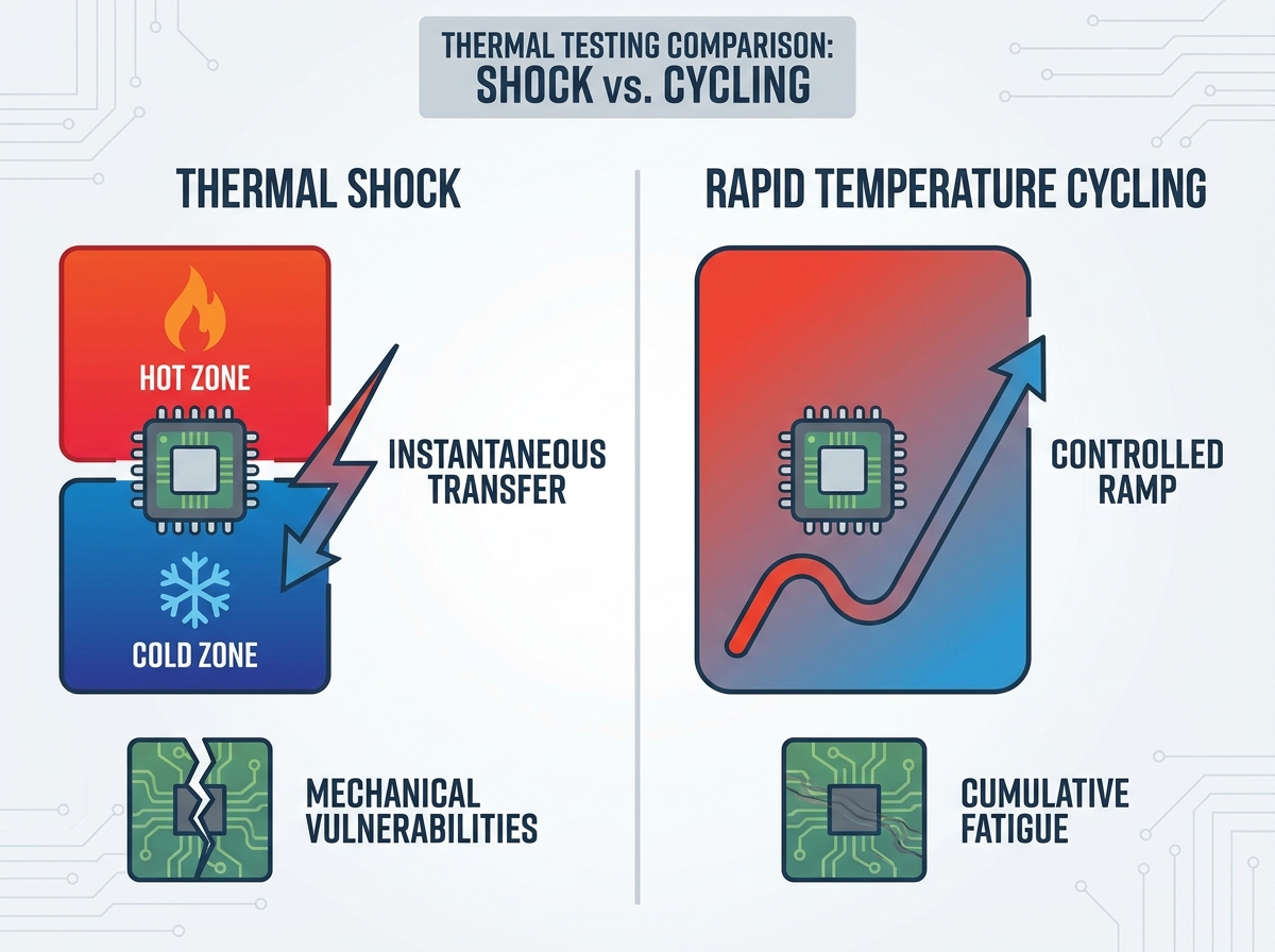
Transition Speed: Thermal shock relies on instantaneous transfer (often < 1 minute) between temperature extremes, while temperature cycling uses controlled ramp rates (e.g., 5°C to 15°C per minute).
Failure Mechanisms: Thermal shock excels at exposing mechanical vulnerabilities (CTE mismatches, brittle fractures), whereas cycling simulates accelerated life fatigue (solder joint degradation, cumulative stress).
Equipment Distinction: The test dictates the asset. Thermal shock requires dual-zone or elevator-based configurations; temperature cycling utilizes a single-zone chamber with high-capacity compressors.
Standard Alignment: Selection is largely governed by end-use application standards (e.g., MIL-STD, IEC, JEDEC) and the specific physical properties of the Device Under Test (DUT).
To properly evaluate thermal shock vs temperature cycling, engineers must first analyze the core thermodynamic principles. Each test applies stress differently. Understanding these mechanical differences prevents critical testing errors.
Thermal shock testing applies immense, sudden stress. It involves physically moving the Device Under Test (DUT) between two distinct temperature zones. Test operators usually maintain one zone at extreme heat and the other at deep cold. Some systems use extreme fluid or air blasts instead of physical transfer.
Recovery times and transfer times represent the most critical metrics here. The transfer must occur rapidly, often in under ten seconds. This speed creates immediate, violent thermal gradients across the component. The exterior of the device expands or contracts instantly. Meanwhile, the interior mass remains at the previous temperature. This differential causes severe mechanical strain.
Rapid temperature cycling takes a completely different approach. Operators conduct this test within a single workspace. The ambient air temperature changes at a predefined, continuous rate. Engineers program specific ramp rates, such as 10°C per minute.
This controlled approach ensures the entire DUT reaches the target temperature simultaneously. Engineers calculate specific "soak times" based on the product's thermal mass. Proper soaking guarantees the internal mass matches the surface temperature. Cycling provides controlled environmental stress screening (ESS). It pushes the product to its limits without exceeding realistic operational boundaries.
Mechanics Comparison Summary
Testing Metric | Thermal Shock | Rapid Temperature Cycling |
|---|---|---|
Transition Method | Physical transfer between two distinct zones | In-place ramping within a single zone |
Transition Speed | Instantaneous (usually < 1 minute) | Controlled linear ramp (e.g., 5°C–15°C/min) |
Thermal Gradient | Violent differential between surface and core | Uniform temperature distribution throughout |
Primary Goal | Force immediate mechanical failure | Simulate accelerated life fatigue |
Selecting the right test requires understanding your target failure mechanisms. Different environmental stresses expose entirely different vulnerabilities in materials and electronics.
Shock testing acts as a brutal mechanical stressor. It violently pulls apart materials possessing different physical properties. Key vulnerabilities include:
Mismatched Coefficients of Thermal Expansion (CTE): Adjacent materials expand at different rates. When subjected to sudden temperature shifts, the bond between them shears.
Material Delamination: Printed circuit boards (PCBs) and integrated circuit (IC) packaging layers often peel apart. The sudden gradient destroys the adhesive bonds.
Structural Rupture: Hermetic seals and rigid epoxies undergo cracking or crazing. They cannot flex fast enough to accommodate the instantaneous thermal transfer.
Cycling testing mimics years of field use compressed into a shorter timeframe. It reveals long-term wear and tear rather than sudden breakage. Key vulnerabilities include:
Cumulative Fatigue and Creep: Materials slowly deform over prolonged use. Continuous expansion and contraction cycles wear down structural integrity.
Solder Joint Degradation: Electrical connections degrade slowly. Solder joints crystalize and eventually fracture after hundreds of thermal cycles.
Gradual Deformations: Certain mechanical warpages only manifest after repeated, continuous thermal shifts. These would remain invisible during a single rapid shock event.
Testing alone does not complete the QA process. You must conduct rigorous post-test validation. Functional testing on a Printed Circuit Board Assembly (PCBA) remains strictly required after either test. Visual inspection alone fails to spot critical defects.
Micro-cracks in solder joints frequently cause intermittent electrical opens or shorts. These cracks often close up at room temperature. They only disrupt the circuit when the board is hot or cold. Comprehensive functional testing verifies true electrical performance. It catches the invisible damage visual checks miss.
The specific test methodology strictly dictates your hardware assets. You cannot properly perform a true shock profile in a standard cycling unit.
Deploying a thermal shock chamber requires evaluating specialized architecture. Manufacturers primarily build basket/elevator systems. These move the product mechanically between hot and cold air zones (air-to-air). Alternatively, liquid bath systems (liquid-to-liquid) drop the product into alternating fluid vats for maximally aggressive heat transfer.
These units generally demand a larger physical footprint. They require multiple, distinct temperature zones to operate simultaneously. Energy consumption remains consistently high. The system must continuously maintain two extreme temperature environments. It consumes substantial power even when the basket sits idle in one zone.
Conversely, a rapid temperature change chamber features a single-zone workspace. This architecture relies on robust refrigeration and powerful heating elements. Together, they achieve strict linear ramp rates within that solitary space.
These units provide superior operational flexibility. Engineers use them for broader ESS applications, humidity integration, and general life-cycle testing. They also offer better capacity advantages. Elevator baskets have strict weight limits. Single-zone chambers easily accommodate larger, heavier, or highly massive product batches. You can roll heavy racks directly into the workspace.
Your end-use application ultimately dictates your testing protocol. Regulatory bodies enforce strict standards to ensure consumer safety and operational reliability.
Defense applications demand absolute ruggedness. Engineers frequently evaluate MIL-STD-883 and MIL-STD-202 requirements for shock testing on ruggedized electronics. These standards simulate catastrophic scenarios. Think of a missile leaving a warm submarine and instantly entering freezing ocean water.
You must understand exactly when the Department of Defense requires true shock versus accelerated cycling. Substituting a slow ramp rate when a MIL-spec demands instantaneous transfer will result in audit failures.
Consumer electronics rely on different frameworks. Test engineers apply the JESD22-A104 standard for temperature cycling of solid-state devices. This standard focuses heavily on solder joint reliability over a typical consumer lifespan.
Furthermore, adhering to IEC 60068 standard profiles ensures global market compliance. These standards dictate specific ramp rates and soak times. They ensure electronic components survive international shipping and standard daily usage without failing.
Compliance means nothing without proof. Precise data logging provides necessary traceability. You must prove compliance during strict audits. Measuring chamber air temperature alone often proves insufficient.
Best practices dictate placing thermocouples directly on the DUT. The air might reach 85°C in five minutes, but a heavy copper component might take twenty minutes to reach that same temperature. Audits require data proving the product itself reached the target stress level.
Applying the wrong thermal stress ruins products or passes flawed designs. Engineers must balance their testing rigor against realistic field conditions.
Over-testing destroys viable products. Subjecting commercial-grade plastics or standard PCBs to thermal shock often induces structural failures. These specific failures would never actually occur in nature. A consumer smartphone will never experience a ten-second drop from 100°C to -40°C. Forcing this failure leads to unnecessary, expensive redesign costs.
Under-testing carries even deadlier consequences. Consider aerospace or automotive components. An aircraft engine control unit experiences real-world instantaneous shifts during high-altitude startup in arctic conditions. Using a slow temperature cycle for these components misses the brutal mechanical shear they will face. This oversight risks catastrophic field failure and potential loss of life.
Engineers must carefully factor in the thermal mass of the DUT. Physics dictates how quickly a part absorbs or sheds heat. This concept is known as thermal lag.
A rapid temperature change chamber may inadvertently act like a shock chamber to a very small component. A two-gram microchip heats up instantly, experiencing severe stress. Conversely, a heavy steel assembly may not experience true "shock" even in a multi-zone chamber. The massive steel block simply absorbs the heat too slowly. The thermal lag protects the core, invalidating the shock test data.
Decision Framework Guidelines
Application Scenario | Recommended Test Method | Reasoning |
|---|---|---|
Military / Aerospace Ruggedness | Thermal Shock | Simulates extreme, unnatural transitions required by MIL-spec standards. |
Hermetically Sealed Components | Thermal Shock (Liquid) | Finds micro-fractures in seals through immediate violent contraction. |
Production-level ESS | Temperature Cycling | Weeds out infant mortality defects without destroying the whole batch. |
Commercial Warranty Prediction | Temperature Cycling | Simulates years of standard diurnal temperature shifts accurately. |
Use shock testing for early R&D ruggedness discovery. It pushes materials to their absolute physical breaking points. It also satisfies strict MIL-spec compliance. Use temperature cycling for production-level ESS. It provides reliable warranty prediction and commercial reliability testing without inducing false failures.
The choice between thermal shock and rapid temperature cycling is not a matter of testing rigor. It relies entirely on matching thermal physics to expected failure mechanisms and compliance standards. Selecting the right profile ensures you catch defects before they reach the field. It also prevents you from chasing phantom failures in the lab.
To implement an effective testing strategy, follow these actionable next steps:
Assess the thermal mass of your typical DUT to understand its specific thermal lag characteristics.
Audit your required industry testing standards (MIL-STD, IEC, JEDEC) to determine mandated transition speeds.
Evaluate your primary failure concerns. Decide if you are hunting for mechanical CTE shear or long-term solder fatigue.
Consult with an application engineer to determine precise chamber specifications. You must finalize required ramp rates, zone configurations, and workspace volumes.
A: Generally, no. Even chambers with extremely fast ramp rates (e.g., 20°C/min) cannot replicate the near-instantaneous transfer (< 10 seconds) achieved by the dual-zone architecture of a dedicated thermal shock chamber. True shock requires immediate thermal gradient formation, which linear ramping prevents.
A: Ramp rates are dictated by industry standards (e.g., JEDEC) and the DUT’s thermal mass. Rates typically range from 5°C to 15°C per minute. This specific pace ensures internal components soak properly without lagging too far behind the chamber air temperature.
A: Liquid-to-liquid provides significantly faster heat transfer and more severe thermal stress. It proves ideal for hermetically sealed components. Air-to-air represents the standard for unsealed electronics, PCBAs, and larger assemblies where liquid immersion is destructive or impractical.


