
close
Choose Your Site
Global
Social Media

Views: 0 Author: Site Editor Publish Time: 2026-10-07 Origin: Site


Reliable product testing demands exact environmental replication to ensure valid, actionable results across every testing cycle. When you evaluate a component's endurance, you naturally expect your equipment to deliver absolute precision without question. Unfortunately, uneven environmental results routinely compromise product validation efforts across many modern laboratories. Even premium chambers suffer from severe spatial gradients and aggressive temporal fluctuations if improperly configured, loaded, or maintained. These hidden variances quietly skew vital data, leading to dangerous false positive passes or costly, unwarranted product redesigns.
We will explore exactly why these frustrating environmental discrepancies happen and how you can permanently fix them. You will discover a comprehensive diagnostic framework to identify specific uniformity failures within your current testing setup. Furthermore, we will establish rigorous, actionable criteria for evaluating replacement chambers or scheduling corrective calibration services to restore baseline accuracy.
Temperature humidity chamber uniformity is driven by a delicate balance of mechanical airflow, sensor accuracy, and internal thermal mass.
Poor temperature chamber airflow design or improper product loading accounts for the majority of uneven test profiles.
Routine humidity chamber calibration using NIST-traceable standards is non-negotiable for identifying sensor drift before it skews test data.
Evaluating a new chamber requires scrutinizing active airflow management, control system responsiveness, and spatial gradient specifications over raw temperature ranges.
You must define "uneven results" technically to properly diagnose your equipment. Engineers differentiate these errors into two distinct categories: spatial gradients and temporal fluctuations. Spatial gradients mean the temperature or humidity varies depending on where you place the sensor inside the workspace. For example, the front-left corner might measure significantly colder than the center. Temporal fluctuations mean the conditions constantly change over time at a single, fixed location. Both phenomena destroy the validity of your testing data.
Achieving reliable temperature humidity chamber uniformity is critical for stringent regulatory compliance. Industry standards heavily dictate permissible environmental variances. For instance, MIL-STD testing for military components, IEC protocols for electronics, and ICH guidelines for pharmaceutical stability leave zero room for unmapped gradients. If your equipment fails to meet these rigorous metrics, your entire research and development team faces massive operational risks.
Ignoring these chamber gradients invites severe financial consequences. False positives routinely send defective products into mass production, setting the stage for catastrophic field failures. Conversely, false negatives force your engineering teams into endless, unnecessary redesign loops. You face severely delayed time-to-market schedules. Devastating product recalls loom over your brand reputation. Furthermore, invalidated test batches waste months of expensive laboratory runtime, forcing you to restart long-term environmental profiles from scratch.
Why do premium chambers suddenly drift from their programmed setpoints? Three primary physical culprits usually drive these uneven profiles. First, consider the silent threat of sensor degradation. Continuous exposure to extreme humidity environments slowly degrades both capacitive sensors and traditional wet/dry bulb systems. The delicate polymer layers inside modern capacitive sensors absorb microscopic impurities over thousands of hours. They gradually lose their sensitivity, causing the control system to misinterpret the actual internal environment.
Second, seal and gasket failures routinely compromise the isolated environment. Heavy usage compresses the silicone gaskets around the main chamber door. Over time, these materials harden and crack. Micro-leaks form, allowing ambient laboratory air to seep inside the workspace continuously. This intrusion creates localized cold or dry pockets right next to the door seal, violently skewing the gradient data for any products placed nearby.
Third, compressor and heater cycling can easily wreak havoc on environmental stability. Aggressive, poorly tuned PID control loops constantly overcompensate. If the proportional band is too narrow, the system triggers rapid, intense heating or cooling bursts. These aggressive bursts cause severe temperature overshoots. The chamber desperately struggles to achieve internal stabilization, leaving you with wildly fluctuating conditions that ruin sensitive electronic components.
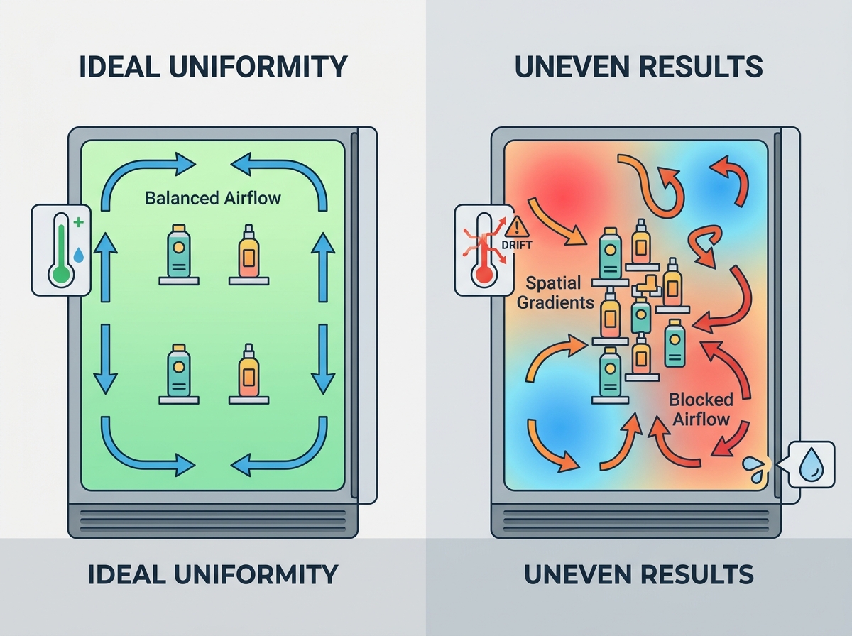
Managing mechanical air movement is arguably the most critical factor in achieving environmental consistency. We must closely examine temperature chamber airflow dynamics to understand exactly why stagnant zones form. Manufacturers typically design high-performance chambers with vertical, horizontal, or mixed airflow patterns. Each specific design serves a distinct testing purpose. Horizontal airflow works exceptionally well for heavily loaded shelves filled with flat circuit boards. Vertical airflow suits tests where complex mechanical items hang suspended. The ultimate goal remains identical across all configurations: prevent stagnant air pockets where dangerous heat accumulates.
Well-engineered baffle and plenum designs make this level of control possible. Advanced plenums distribute air velocity evenly across all shelving levels. They prevent the blower motor from forcing harsh, aggressively conditioned air directly onto your test subjects. Direct air impact instantly causes rapid, localized temperature spikes that ruin test validity.
When you evaluate testing equipment, you must look far beyond raw heating and cooling rates. We strongly advise buyers to evaluate the cubic feet per minute (CFM) relative to the total workspace volume. High CFM ensures rapid air turnover. This high turnover directly minimizes spatial gradients by constantly mixing the internal atmosphere before temperature layers can settle.
Even the most technologically advanced chamber will fail uniformity audits if you load it incorrectly. Implementation reality often clashes with ideal, empty-chamber laboratory conditions. The infamous "blockage" effect happens when technicians densely pack test items on a single shelf. This heavy physical mass completely disrupts the necessary return air paths. Consequently, the upstream side of your load receives the full force of the conditioned air. It often over-cools or over-heats. Meanwhile, the downstream side sits hopelessly in a stagnant shadow, never reaching the programmed target setpoint.
Testing live loads complicates this equation significantly. When you test active, powered devices like battery packs or running electronics, they emit their own thermal energy. This localized heat generation fiercely fights against the chamber's internal control systems. Testing active loads requires specialized chamber compensation features to pull that excess heat away rapidly without over-cooling the rest of the workspace.
Follow these established best practices to prevent product placement from skewing your data:
Leave at least two to three inches of clear space between the chamber walls and your test items.
Stagger items across multiple shelves to allow conditioned air to flow smoothly through the vertical gaps.
Place high-heat dissipating live loads closer to the return air ducts.
Never exceed the manufacturer's recommended total thermal mass limit for your specific chamber model.
You must clearly differentiate between a sudden component failure and the insidious nature of slow sensor drift. A broken compressor is highly obvious; the chamber simply stops working and triggers a loud alarm. Slow sensor drift remains entirely invisible. It quietly shifts your test conditions away from reality over several months, contaminating massive amounts of data.
Routine, rigorously documented humidity chamber calibration stops this drift from ruining your operations. You absolutely cannot rely on a single-point center reading to verify performance. Single-point checks ignore spatial gradients entirely. Instead, you must demand multi-point, spatial calibration protocols using NIST-traceable standards. Qualified technicians should use 9-point or 15-point thermocouple arrays mapped across the entire workspace to capture a true three-dimensional picture of the environment.
However, we must maintain realistic assumptions regarding this process. Calibration only verifies sensor accuracy at one specific moment in time. It cannot physically fix an underlying mechanical airflow issue. It cannot repair degraded polyurethane insulation. Calibration simply tells you if your electronic control system accurately reads the physical environment it creates. If the environment itself is physically flawed due to poor design, calibration only confirms the bad news.
Sometimes, extensive calibration and preventative maintenance cannot rescue an aging, obsolete system. When shortlisting a replacement, map technical specifications directly to your required business outcomes. Advanced PID controllers and modulated refrigeration valves do not just sound impressive on a brochure. They actively deliver tighter uniformity tolerances and permanently prevent damaging thermal overshoots.
Scalability and strict regulatory compliance matter immensely in modern manufacturing. Modern control software must log verifiable, tamper-proof environmental data. This automated documentation satisfies strict Quality Management Systems (QMS) during hostile audits. When vetting potential vendors, demand hard proof before purchase. Shortlist manufacturers who willingly provide Factory Acceptance Testing (FAT) data. This specific data must mathematically prove spatial uniformity at your exact extreme temperature and humidity setpoints, not just at simple, ambient laboratory conditions.
Technical Feature | Primary Function | Business Outcome |
|---|---|---|
Advanced PID Controllers | Actively predict and adjust heating/cooling cycles. | Eliminates temporal fluctuations and rapid thermal overshoots. |
Modulated Refrigeration Valves | Provide precise, variable cooling capacity. | Maintains highly stable low-load conditions efficiently. |
Engineered Plenums | Distribute air evenly across all internal zones. | Reduces spatial gradients and eliminates stagnant dead spots. |
Encrypted Data Logging | Records tamper-proof environmental statistics. | Ensures immediate QMS and regulatory audit compliance. |
Uneven chamber results are rarely an unsolvable mystery. They consistently stem from a highly solvable mix of operational discipline and pure mechanical capability. By deeply understanding internal airflow dynamics, respecting thermal mass limits, and aggressively maintaining your sensors, you can permanently restore testing integrity.
Take proactive steps today to secure your valuable data. We highly recommend you schedule a professional 9-point spatial mapping audit of your current testing chamber. This will quickly identify hidden dead zones that threaten your product validation. If your current equipment cannot maintain the strict tolerances your industry requires, request a technical consultation immediately to explore a high-uniformity replacement chamber.
A: Standard industry tolerances typically range from ±0.5°C to ±2.0°C for temperature, and ±2% to ±5% for relative humidity. However, acceptable limits depend entirely on your specific regulatory requirements. Aerospace and pharmaceutical testing often demand the tightest tolerances. General electronic component screening may allow slightly wider margins. Always reference your specific MIL-STD, IEC, or ICH guidelines to define acceptable variance for your products.
A: No, adjusting the PID controller primarily fixes temporal fluctuations, such as aggressive temperature overshoots or unstable cycling over time. Spatial gradients—where one specific corner of the chamber is physically hotter than another—are mechanical issues. Fixing gradients usually requires physical adjustments like altering airflow velocity, redesigning baffles, or correcting how you load products onto the shelves.
A: You should establish a strict annual baseline for all standard testing equipment. However, high-stress applications in aerospace, automotive, or pharmaceutical sectors require much more frequent checks. For chambers running continuous, extreme environmental profiles, we highly recommend bi-annual or even quarterly schedules. Frequent multi-point mapping catches insidious sensor drift before it permanently invalidates weeks of costly research data.
A: Yes, internal volume significantly impacts airflow dynamics. Maintaining consistent air velocity across a massive walk-in chamber requires exponentially more engineering than a small benchtop model. Larger internal distances heavily increase the risk of stagnant zones and thermal loss. Manufacturers must utilize extremely powerful blower motors, complex plenum structures, and strategic return ducts to ensure conditioned air reaches every corner evenly.


