
close
Choose Your Site
Global
Social Media

Views: 0 Author: Site Editor Publish Time: 2026-10-10 Origin: Site


Selecting the wrong testing method poses severe engineering risks. It yields inaccurate toughness data. You risk mischaracterizing polymer performance and inviting downstream product failures. Arbitrary testing protocols simply have no place in modern manufacturing. Impact testing strictly evaluates a plastic’s capacity to absorb energy during high-speed collisions. We rely on this critical data to ensure parts endure sudden real-world stresses. Manufacturers depend on precise metrics to prevent catastrophic snapping or shattering in end-user applications.
This article serves as a technical evaluation guide. It helps lab managers, QA engineers, and material specifiers definitively choose between two primary methodologies. You will learn to navigate decisions based on specimen geometry, international standards, and real-world failure modes. Our comprehensive breakdown of charpy vs izod impact testing provides the actionable clarity you need for rigorous, reliable quality control.
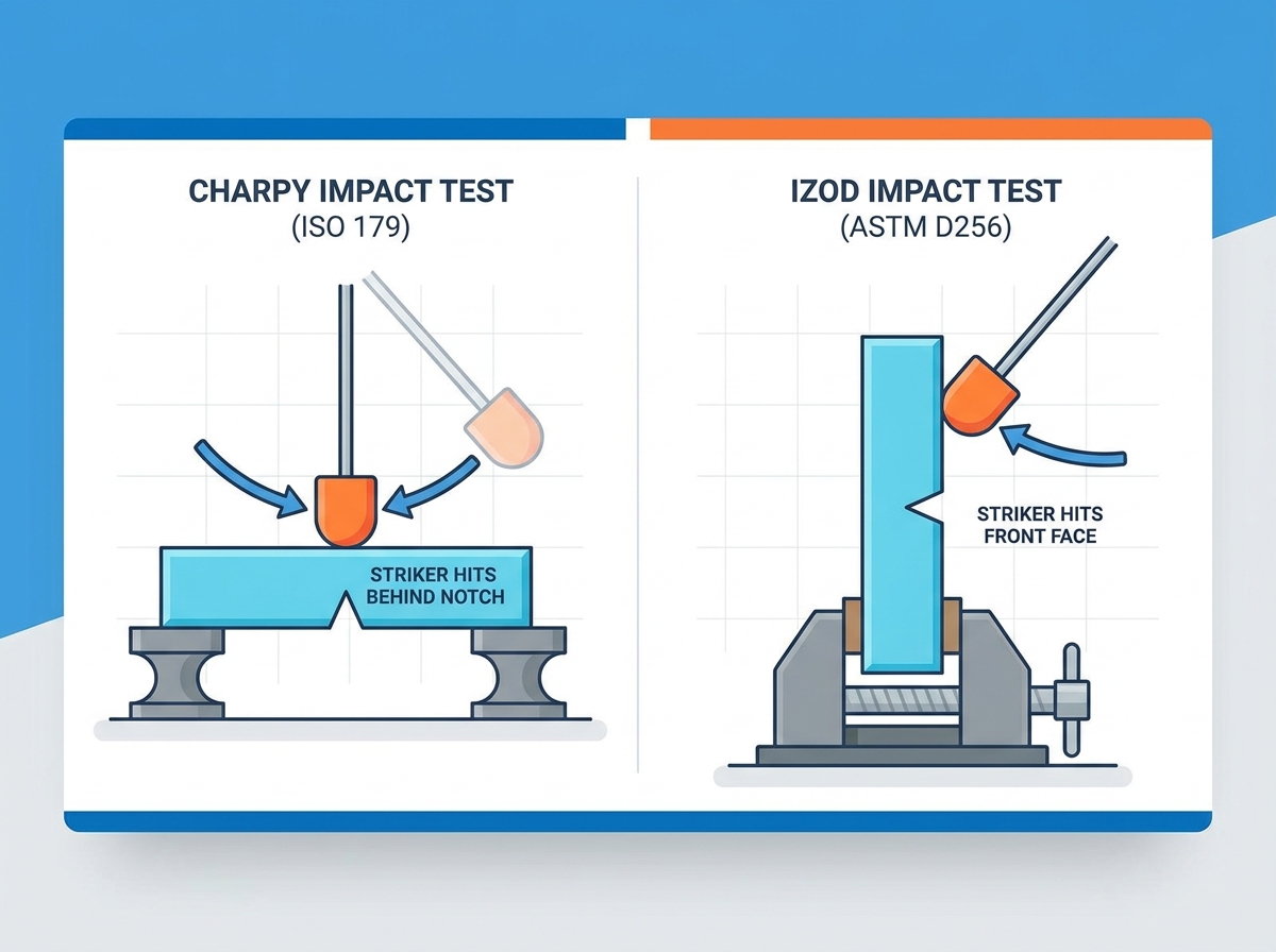
Orientation Dictates the Test: Charpy tests utilize a three-point bending configuration with a horizontally supported specimen, while Izod tests use a cantilever beam configuration with a vertically clamped specimen.
Standards Drive Selection: The choice often hinges on regional and industry compliance requirements, with ISO heavily favoring Charpy for plastics (ISO 179) and ASTM traditionally leaning toward Izod (ASTM D256).
Notch Integrity is Critical: Accurate impact notch preparation (V-notch or U-notch) is the most common failure point in lab repeatability; micro-machining errors drastically skew brittle-ductile transition data.
Material Sensitivity: Izod is highly sensitive to notch geometry and clamping pressure, making Charpy generally more reliable for testing unnotched or highly brittle polymers.
Understanding the fundamental mechanics of pendulum impact tests ensures you capture accurate material behavior. Both tests utilize a swinging pendulum to break a plastic specimen. They measure the kinetic energy lost during fracture. However, their physical configurations differ significantly. These variations produce distinct baseline values and reveal different material weaknesses.
In a Charpy setup, the specimen lies horizontally. It rests against supports at both ends. The pendulum strikes the exact center of the sample, directly behind the notch. This creates a three-point bending scenario. The specimen faces no clamping pressure, allowing the material to flex and break naturally under impact.
Conversely, the Izod test clamps the specimen vertically. It functions as a cantilever beam. The pendulum strikes the upper exposed face. It hits the same side as the machined notch. This vertical, clamped position introduces localized stresses near the vise jaws. The lower half remains locked, while the upper half snaps off upon impact.
Both methods calculate toughness by measuring the pendulum's energy loss. The machine registers the starting height and the final height after the strike. The difference equals the absorbed energy. Yet, they yield varying baseline values. Izod tests lose some energy to clamping friction and localized compression. Charpy tests direct nearly all energy into the sample fracture. You cannot directly compare these raw values due to these differing strike dynamics.
Table 1: Operational Comparison of Pendulum Testing Methods
Feature | Charpy Test | Izod Test |
|---|---|---|
Specimen Position | Horizontal | Vertical |
Support Type | Supported at both ends (unclamped) | Clamped at the base (cantilever) |
Strike Location | Center, opposite the notch | Upper tip, same side as the notch |
Primary Stress Mode | Three-point bending | Cantilever snapping |
Engineers must match the test to expected field failures. Charpy testing effectively simulates structural beams, automotive bumpers, and impact-resistant housings. It mimics scenarios where a part takes a hit directly in the middle while supported at its edges. Izod testing replicates parts subjected to cantilevered loads. Use it to simulate gear teeth, protruding levers, or any component vulnerable to snapping forces at a fixed base.
Consistency starts long before the pendulum swings. Preparing a reliable plastic impact test specimen demands strict attention to dimensional geometry. Any slight deviation in sample thickness or width drastically alters the resulting energy absorption data.
Specimen geometries vary heavily between ASTM and ISO methodologies. ISO 179 often utilizes an 80 mm x 10 mm x 4 mm specimen for Charpy tests. ASTM D256 typically requires a 63.5 mm x 12.7 mm x 3.2 mm geometry for Izod tests. You must strictly adhere to the designated standard parameters. A thicker sample requires exponentially more energy to break. Comparing an ASTM sample to an ISO sample yields useless analytics.
Clamping pressure introduces a massive variable in vertical tests. Overtightening the vise jaw on an Izod specimen causes premature stress concentrations. It crushes the polymer matrix slightly, weakening the base. Undertightening allows the specimen to shift upon impact, absorbing kinetic energy and artificially inflating the toughness score. Charpy's simple resting placement entirely eliminates these clamping-induced stress concentrations. This makes Charpy naturally more repeatable across different technicians.
Injection-molded plastics exhibit severe anisotropy. The polymer chains align along the mold's flow direction during manufacturing. This orientation heavily impacts structural toughness. A part might survive a massive blow perpendicular to the flow lines but shatter from a light tap parallel to them. You must test samples in orientations that align with expected real-world stress vectors.
Always record the injection flow direction on your test sheets.
Cut specimens both parallel and perpendicular to flow lines for a complete material profile.
Ensure technicians load the samples into the anvil in the correct orientation every single time.
A flawless sample means nothing if the notch is flawed. Reliable impact notch preparation separates professional laboratories from amateur operations. The notch essentially simulates a design flaw, a sharp internal corner, or a localized scratch on your final product.
Many assume the notch simply forces the specimen to break. This is inaccurate. Notches act as deliberate stress concentrators. They measure notch sensitivity and crack propagation dynamics rather than just crack initiation. By focusing the impact energy into a microscopic area, they reveal how a polymer behaves once its outer skin is compromised.
Engineers typically utilize two specific geometries depending on the material's inherent brittleness:
V-Notch: This represents the industry standard for most rigid plastics. It demands strict radius requirements, often cut to a 0.25 mm base radius. It provides a sharp, concentrated point to evaluate standard crack propagation.
U-Notch: Technicians use this profile for highly notch-sensitive materials. Some polymers shatter prematurely with a V-notch, yielding unrepresentative data. The wider radius of a U-notch provides a gentler stress concentration, allowing for more nuanced data on brittle-ductile materials.
Micro-machining errors remain the most common failure point in lab repeatability. Poor milling techniques induce thermal degradation. Friction from a dull cutter melts the polymer at the base of the notch. This blunts the intended radius and drastically skews brittle-ductile transition data. Furthermore, microscopic cutter marks create secondary stress points, causing premature fractures.
Tooling selection is critical: Single-tooth broaching or specialized motorized notchers ensure repeatable quality control. Multi-tooth cutters often generate excess heat. You must utilize equipment designed specifically for polymers, operating at optimal cutting speeds with constant cooling profiles if necessary.
Selecting an impact test frequently comes down to regulatory obligations. The global manufacturing sector operates under strict compliance frameworks. You must produce data that satisfies your specific regional and industrial clients.
The global automotive and aerospace sectors increasingly standardize on ISO 179 for thermoplastic and thermosetting molding materials. ISO standards heavily favor the Charpy configuration. They demand rigorous geometric consistency and often integrate seamlessly with modern European and Asian manufacturing requirements.
Conversely, North American markets heavily lean toward ASTM D256. This standard primarily utilizes the Izod configuration. Legacy quality control systems and thousands of existing material data sheets (TDS) in the US rely on this framework. If you supply parts to legacy American manufacturers, you must often maintain ASTM capabilities.
Common Mistake: Many engineers attempt to convert ASTM Izod numbers to ISO Charpy numbers. This is technically invalid.
ASTM reports impact strength based on the sample's thickness (typically Joules per meter, or J/m). ISO reports the energy relative to the cross-sectional area behind the notch (typically kilojoules per square meter, or kJ/m²). Because they utilize different specimen geometries, strike locations, and mathematical baseline calculations, the results are not directly convertible. You cannot use a mathematical formula to swap one for the other.
When auditors evaluate your impact testing procedures, they look far beyond the pendulum swing. They scrutinize the entire lifecycle of the specimen. To ensure compliance, labs must document:
Specimen Conditioning: Plastics absorb moisture. Auditors check humidity logs in your conditioning chambers.
Temperature Control: Polymer toughness fluctuates wildly with temperature changes. Technicians must transfer samples from the freezer to the anvil in under five seconds during cold-weather testing.
Equipment Calibration: Pendulum friction, windage losses, and anvil alignment require certified annual calibrations.
Your laboratory needs a practical decision matrix. You must balance material science principles with everyday operational realities. Neither test is inherently superior; they simply serve different analytical purposes.
Your daily material portfolio should heavily influence your primary testing methodology.
Recommend Charpy for: Brittle materials, fiber-reinforced composites, and unnotched testing. Because Charpy requires no clamping, it eliminates the risk of crushing delicate composites or fracturing brittle polymers before the test even begins.
Recommend Izod for: Ductile polymers like Polycarbonate (PC) or ABS. Izod effectively evaluates the notch sensitivity of flexible materials that might otherwise bend completely through a Charpy anvil without snapping.
High-volume manufacturing demands rapid testing turnaround. Operational throughput varies between the two setups. Charpy testing is significantly faster for large batches. The technician simply places the specimen across the supports and releases the pendulum. Izod testing requires the operator to precisely align the sample vertically, tighten the clamp to a specific torque, and unclamp it afterward. Over hundreds of daily samples, Charpy saves substantial labor hours.
Many modern laboratories struggle with limited floor space. Dedicating separate benches to Charpy and Izod machines restricts growth. Invest in universal pendulum impact testers. These modern systems come equipped with interchangeable fixtures and dual-purpose strikers. They allow technicians to swap from an ISO 179 Charpy setup to an ASTM D256 Izod setup in minutes. This versatility supports multiple compliance methodologies without sacrificing lab footprint.
The debate between Charpy and Izod methodologies rarely centers on which test is inherently "better." It comes down to aligning your lab capabilities with regulatory demands, material behaviors, and historical data baselines. Both tests deliver critical insights into polymer toughness and notch sensitivity. Your choice dictates how accurately you predict real-world product durability.
Take immediate action to secure your testing accuracy. First, audit your current notch preparation processes to eliminate friction-induced polymer degradation. Next, review your primary material data sheet requirements to ensure your output metrics match client expectations. Finally, consult with a testing equipment manufacturer to configure a dual-capable pendulum tester. Upgrading your lab infrastructure ensures you remain compliant, versatile, and technically unassailable.
A: No. Due to differing specimen geometries, distinct strike locations, and completely different clamping methods, there is no reliable mathematical correlation between the two for plastics. You must perform the specific test requested by the material standard.
A: Certain highly impact-resistant polymers or fiber-reinforced composite matrices will not break if unnotched. Conversely, adding a notch to some highly brittle materials causes unrepresentative, catastrophic failure that simply does not reflect the end-use product's actual geometry.
A: Polymers exhibit distinct brittle-ductile transitions at varying temperatures. A plastic that flexes at room temperature may shatter like glass at freezing temperatures. Standardized testing (often at -30°C, 0°C, or 23°C) is required to simulate operational environments, making rapid transfer from the conditioning chamber to the anvil absolutely critical.


