
close
Choose Your Site
Global
Social Media

Views: 0 Author: Site Editor Publish Time: 2026-09-05 Origin: Site


Achieving precise test data requires more than just pushing a button on a sophisticated control panel. It depends heavily on how well your test samples interact within the physical workspace. Improper equipment sizing introduces costly operational risks for any testing laboratory. Undersized chambers severely restrict vital airflow and invalidate critical test data. Conversely, oversized units waste premium floor space, drastically inflate utility bills, and significantly slow down thermal transition rates.
True environmental test chamber sizing goes beyond measuring simple internal volume. It involves a complex calculation of thermal mass, active heat loads, and rigid facility constraints. This guide provides test engineers and procurement teams with an evidence-based framework. You will learn how to calculate your exact capacity needs accurately. We also explore how to shortlist the correct chamber architecture to guarantee reliable, repeatable testing results across your entire product development cycle.
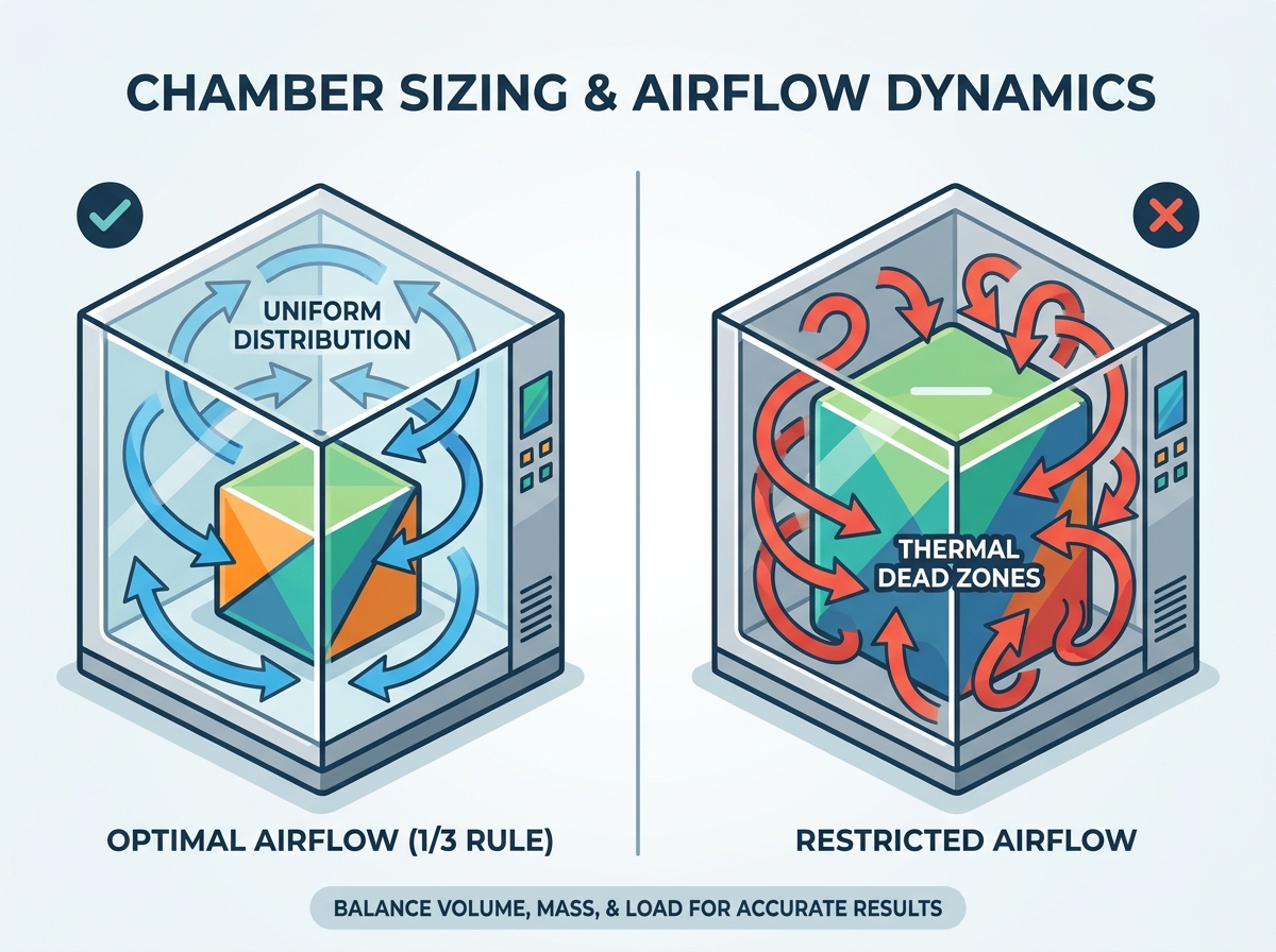
Airflow is the limiting factor: Test samples should occupy no more than 1/3 of the internal chamber volume to ensure uniform temperature and humidity distribution.
Sample mass dictates performance: Dense test items absorb thermal energy, directly impacting the chamber's ability to meet required temperature pull-down and heat-up rates.
Active vs. Passive loads: Powered electronic samples generate heat (live loads), requiring a larger refrigeration capacity regardless of physical dimensions.
Facility constraints override internal needs: A chamber’s external footprint, access pathways (doors/elevators), and power requirements must align with facility realities before purchase.
Engineers often assume they can fill a chamber's internal workspace from wall to wall. This is a critical mistake. Industry standards heavily rely on the "1/3 Rule." This rule dictates your test samples should occupy a maximum of 33% of the internal workspace. We follow this ratio to guarantee unhindered airflow.
Conditioned air must circulate freely around every single test item. When you pack a chamber too tightly, you create airflow blockages. These blockages lead to thermal dead zones. In these dead zones, the actual temperature deviates significantly from the setpoint displayed on your controller. Your sensors might register 85°C, but the blocked sample might only experience 70°C. This discrepancy invalidates your test data completely.
Physical clearance around your samples is non-negotiable. You must strategically position items to prevent airflow blockage from the conditioning plenum. Proper baffling ensures conditioned air reaches all corners.
Wall Clearance: Maintain a minimum of two to three inches of open space between your samples and the interior walls.
Vertical Spacing: Leave adequate room at the top and bottom of the chamber. Air typically enters from the top or back and returns through the floor or lower plenum.
Rack Placement: Avoid pushing trays all the way against the back wall. This chokes the primary air return path.
The physical geometry of your product dictates the shape of the chamber you need. Internal volume alone tells an incomplete story. A long automotive drive shaft requires a wide or deep chamber. Stacks of high-density server PCBs demand taller vertical space with multiple shelving tiers. Always map the three-dimensional footprint of your largest anticipated test batch. Choose internal dimensions accommodating this specific footprint while maintaining the strict 1/3 volume ratio.
Physical size is only the first half of the equation. Thermal dynamics represent the second half. Evaluating thermal mass and live loads reveals the true environmental test chamber capacity required for your application.
Every object you place inside the workspace absorbs and releases thermal energy. We call this thermal mass. The physical weight and the material composition of your test sample directly alter the required machinery size. Dense materials demand significantly more heating and cooling power. For instance, cooling a 50-pound solid aluminum engine block requires drastically more refrigeration capacity than cooling 50 pounds of lightweight plastic components.
Different materials possess different specific heat capacities. The chamber must overcome this thermal inertia to achieve your specified temperature transition rates. If you undersize the compressors, the chamber will lag behind your programmed test profile.
Engineers frequently miscalculate total mass by forgetting about support equipment. You must include the weight of every internal accessory.
Commonly forgotten mass includes:
Heavy-duty stainless steel shelving.
Custom mounting fixtures and vibration tables.
Thick power cables and communication harnesses.
Sensor blocks and calibration arrays.
A 30-pound test sample sitting on a 40-pound custom steel fixture creates a 70-pound total thermal load. You must calculate the transition rates using this combined total mass.
Live loads introduce active heat into the environment. When you power on electronic devices during a test, they generate wattage. The chamber’s refrigeration system must constantly battle this generated heat. We call this active heat dissipation.
If you test active electronics, your cooling system requires extra horsepower. The compressor must first overcome the live load wattage before it can begin pulling down the ambient air temperature. A 500-watt live load changes the sizing equation entirely. You must document the maximum expected wattage of your powered samples and present this data to the chamber manufacturer during the specification phase.
Once you define your spatial limits and thermal loads, you must select an appropriate physical architecture. Manufacturers categorize equipment into three primary tiers based on scale and capability.
Benchtop units offer incredible convenience for small-scale testing. They fit easily onto standard laboratory tables. They work best for evaluating small electronic components, sensors, and miniature sub-assemblies. However, they carry strict limitations. Because they utilize smaller refrigeration compressors, benchtops struggle with heavy thermal mass. They rarely achieve rapid extreme temperature transitions exceeding 5°C per minute. They also lack the footprint for bulky items.
Reach-in models serve as the versatile middle ground for most testing facilities. They stand on the floor and accommodate multiple product batches simultaneously. A typical temperature humidity chamber size in this category ranges between 4 to 64 cubic feet. Reach-in units feature powerful cascading refrigeration systems. They confidently handle moderate live loads and achieve highly demanding thermal cycling rates. They are the industry standard for standard consumer electronics, battery cells, and automotive sub-components.
Walk-in and drive-in chambers handle massive, large-scale evaluations. Test subjects include full telecommunications racks, entire vehicles, and large aerospace parts. Sizing these units requires custom structural prerequisites. You must evaluate floor load-bearing capacities carefully. Heavy equipment might require reinforced steel floors. Manufacturers build these units using either modular insulated panels or solid-welded construction. Solid-welded designs better withstand extreme high-humidity and high-temperature combinations.
Chamber Architecture Comparison Chart
Architecture Type | Best Suited For | Typical Volume Range | Transition Speed Capabilities |
|---|---|---|---|
Benchtop | Small components, ICs, limited lab space | 0.5 to 3 cubic feet | Slow to moderate (1°C to 3°C/min) |
Reach-In | Multiple batches, PCB stacks, sub-assemblies | 4 to 64 cubic feet | Moderate to rapid (3°C to 15°C+ /min) |
Walk-In / Drive-In | Vehicles, telecom racks, aerospace parts | 100+ cubic feet | Customized based on specialized mechanicals |
You can calculate internal volume flawlessly and still face a disaster on delivery day. Facility constraints routinely override internal testing needs. You must align the external footprint and facility infrastructure with the equipment specifications before finalizing any purchase.
The journey from the loading dock to the final installation spot contains numerous logistical bottlenecks. Walk through the entire delivery path with a tape measure. You must verify multiple external dimensions.
Measure every single door width along the route. Standard office doors rarely accommodate a 32-cubic-foot reach-in chamber.
Check freight elevator weight limits. Heavy-duty chambers with dual compressors easily exceed passenger elevator capacities.
Evaluate hallway turning radiuses. A long unit might fit through a door but get stuck on a tight 90-degree corner.
Confirm loading dock height and pallet jack accessibility.
Chambers require surrounding space to operate safely. You cannot push an air-cooled unit flush against a back wall or cram it into a tight closet. Air-cooled condensers pull in massive volumes of ambient room air to function. If you restrict this exterior airflow, the machinery overheats and shuts down.
Specify mandatory physical clearance. Standard practice dictates leaving 18 to 24 inches of clearance around the rear and sides of the unit. This space guarantees proper condenser ventilation. It also provides essential room for technicians to access service panels during routine maintenance and calibration.
High-performance testing equipment demands robust utilities. Map your selected size directly to your facility's power capabilities. Small benchtop units might run on standard 120V single-phase power. However, standard reach-in chambers require 208V, 230V, or 460V three-phase power. Supplying inadequate voltage damages delicate internal electronics.
Humidity systems require dedicated water supplies. You must provide demineralized or reverse-osmosis (RO) water to prevent scale buildup on internal heaters. Furthermore, if you specify a massive walk-in unit with a water-cooled condenser, you must ensure your facility possesses a dedicated cooling water loop capable of handling the flow rate.
Sizing equipment based strictly on what you test today often leads to obsolete machinery tomorrow. Smart procurement requires looking ahead.
We advise against sizing your workspace strictly for your current minimum requirements. Product dimensions evolve. Next year’s prototype might be 15% larger or feature a denser internal battery. Recommend adding a 10% to 20% buffer in both physical volume and thermal capacity. This built-in buffer easily accommodates future, larger product iterations. It ensures your lab remains capable without requiring an entirely new capital equipment purchase.
Strict compliance protocols directly dictate your machinery selection. Specific MIL-STD, IEC, or automotive OEM standards enforce rigid thermal transition rates. For example, testing to MIL-STD-810 might force a 5°C to 10°C per minute transition rate. Achieving this aggressive rate requires massive compressor pairings and high-velocity airflow. These rigorous standards force you to select specific dimensions to maintain proper sensor placement and airflow velocity. You cannot separate the physical dimensions from the required regulatory testing standard.
Before you request a quote from a manufacturer, prepare a highly specific data checklist. This ensures the applications engineer can calculate your exact needs.
Maximum external dimensions: What is the largest footprint your lab and doorways can accept?
Total mass: Combine the exact weight of your heaviest test sample and all required racking.
Temperature and humidity ranges: Identify the extreme high and low points.
Required transition rate: State how fast you need to move between temperature extremes (e.g., 5°C/minute).
Live load wattage: Document the maximum heat your active devices will generate during the test.
Proper environmental test chamber sizing requires meticulous balancing. You must balance the physical geometry of your test sample with its complex thermal dynamics. Simultaneously, you must navigate the rigid physical infrastructure of your facility. Overlooking any single variable—from blocking internal airflow to ignoring doorway widths—jeopardizes your testing integrity and operational efficiency.
Take actionable steps to safeguard your test procedures:
Apply the 1/3 Rule strictly to maintain crucial airflow and eliminate thermal dead zones.
Calculate the exact thermal mass of both your product and your support fixtures.
Document all live load wattages before speaking with a supplier.
Measure your entire facility delivery path to prevent installation disasters.
We strongly encourage you to consult with a qualified applications engineer. Submit your specific testing profiles, mass calculations, and spatial constraints directly to them. An expert review guarantees a custom sizing calculation and a precise equipment recommendation tailored specifically to your laboratory needs.
A: Yes, provided they share the exact same unified testing profile. However, you must carefully monitor combined thermal mass to ensure the compressors can handle the load. Also, avoid mixing materials that might off-gas and cause cross-contamination between different sample types.
A: Over-packing severely restricts critical airflow. This creates dead zones where conditioned air cannot reach. Your sensors will misread the ambient environment, causing the controller to record inaccurate data. Ultimately, the system will fail to meet your required temperature transition rates.
A: Routing thick communication and power cables consumes internal physical space and disrupts airflow. Furthermore, open ports introduce significant heat leaks. You must strategically plan port placement and size during the specification phase to prevent these heat leaks from overwhelming the refrigeration capacity.


